

By Steven Dam
We tend to use the terms schema, ontology, and language as synonyms when discussing the basis for capturing information in a database for systems engineering. But are they the same? Let’s look at the definitions of each word.
In the English language, most words are context-sensitive. For example, a general definition of “schema” brings up[1]:
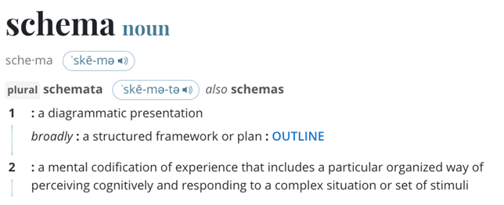
However, we mean it in the context of computer science, database science in particular. Looking at a more technical website, its definition is, “In computer programming, a schema (pronounced SKEE-mah) is the organization or structure for a database, while in artificial intelligence (AI) a schema is a formal expression of an inference rule.”[2] This defines it as the organization of a database.
Looking at Webster’s definition of ontology shows[3]:
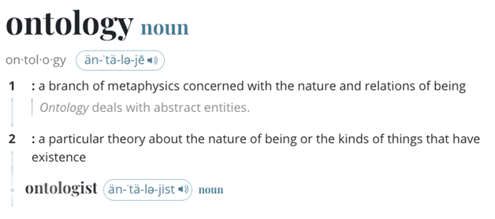
This doesn’t exactly fit the industry’s meaning of ontology. Techopedia says the meaning of ontology is, “Computer ontology refers to the interpretation of a group of ideas within a specific domain that defines the interrelationship between those ideas.” This definition is closer to the one used in systems engineering. The “group of ideas” can also be called a “taxonomy.” So, ontology is the taxonomy and relationships between ideas. This is very much the same as a relational database schema. One of the key ontologies in use is the Basic Formal Ontology (BFO)[4]. The taxonomy is represented by entities, and entities can be anything that exists. The user usually adds attributes to the entities to help describe them more completely. Tools like OWL provide a means for capturing and using ontologies. Most database schemas are expressed as entities, relationships, and attributes (ERA). ERA diagrams and Hierarchy Charts are often used to express database schemas and ontologies. For the systems engineer, these terms seem to be effectively synonyms.
Webster gives many more interpretations of “language.” The figure below is only a portion of the definitions provided.
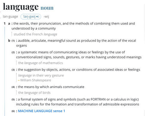
Since Systems Engineering is a disciple of engineering, based on scientific principles, b(2) seems to fit our usage of the word “language.” For example, SysML is considered one of the primary languages in use today. The current version, SysML v1.6, uses diagrams to communicate the ideas of what makes up the system. SysML v2.0 is planning to include a new ontology to enhance communications, particularly between software tools. But since systems engineers aim to capture information in a database, the language needs to be related to a database schema. The use of ontologies can bridge that gap.
Another prevalent systems engineering language is the Lifecycle Modeling Language (LML). LML goes one step further in ontology, by providing attributes on relationships. Thinking of entities as the nouns, relationships as the verbs, and attributes as the adjectives that modify the noun, then attributes on relationships represent the adverbs of language. Other common ontologies do not have adverbs, so instead of modifying the relationship, they often create many more relationships or use some form of symbology to represent the adverb in their language. LML uses the attributes of relationships to reduce the number of relationships required to capture the complexity of a system. LML was developed to improve communication with all the systems engineering stakeholders and provide a language for program management, which is closely related to systems engineering. Some of LML’s entity classes are “Cost,” “Risk,” and “Decision,” and LML also maps to other languages. In fact, it provided an ontology for SysML in 2014.
Another aspect of the LML language is contained in the mandatory diagrams. For simplicity, LML only defines 3 key diagram types: Action (behavioral), Asset (Physical), and Spider (traceability). These three diagram types (shown below) provide the most essential elements of systems engineering. The main difference between LML and languages like SysML is the use of a special case of the Action entity class to represent decision points. All the other languages for systems engineering use symbols for decision points. These symbols are a barrier to communication with other system stakeholders and cannot be allocated to who or what performs them.
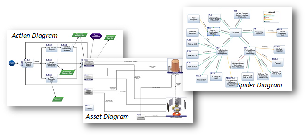
You will want many other diagram types and the LML specification shows many other types as examples, but these three are critical to the systems engineering mission. Tools like Innoslate® automatically generate these diagrams from the data in the database and the rules for the diagram. This language and auto-generation enable us to move from model-based systems engineering (MBSE) to data-driven systems engineering (DDSE), which will find greater acceptance outside the systems engineering community.
[1] Merriam-Webster Online Dictionary, https://www.merriam-webster.com/dictionary/schema, accessed 12-22-2022.
[2] TechTarget Data Management, https://www.techtarget.com/searchdatamanagement/definition/schema, accessed 12-22-2022.
[3] Merriam-Webster Online Dictionary, https://www.merriam-webster.com/dictionary/ontology, accessed 12-22-2022.
[4] Basic Formal Ontology 2.0 – Specification and User’s Guide, Barry Smith, June 26, 2015. This document can be found at https://github.com/bfo-ontology/BFO/wiki, accessed 12-22-2022.
.png?height=200&name=bpmn%20%26%20lml%20(1).png)