


The Lifecycle Modeling Language (LML) was created in 2012 and overseen by the lifecycle modeling...
By Lilleigh Stevie
The Business Process Model and Notation (BPMN) provides a standardized graphical notation for documenting business processes. It is designed to be understandable by all business stakeholders and to model a wide range of business processes. The Object Management Group (OMG) maintains the BPMN standard and has become widely used across the board.
The Lifecycle Modeling Language (LML) specifies a simple ontology with common graphical notations. For example, LML has the Action Diagram that represents the functional sequencing of Actions, along with the data flow provided by Input/Output entities.
Due to the similarities in capturing the sequencing of processes, a mapping between BPMN and LML’s Action Diagram was created to share diagram data between them.
Introduction to the Elements of BPMN and LML
BPMN has four element categories for diagramming: 1) Flow objects, which are objects used to define a process (events, activities, and gateways), 2) Connecting objects, which are used to connect flow objects (message flows, sequence flows, and associations, 3) Swimlanes, which are containers that separate a set of activities from others (pools and lanes), and 4) Artifacts, which provide additional information (data objects, groups, and annotations). The BPMN 2.0 specification additionally defines three basic types of sub-models within a BPMN end-to-end model: 1) Process, 2) Choreographies, and 3) Collaborations, which can include Processes and/or Choreographies.
LML Action Diagrams consist of Actions, Input/Outputs, Resources, and Assets. Actions can be placed in serial or in parallel with control nodes that are specialized Action types, such as Or Action, Sync Action, and Loop Action. Input/Outputs specify the information, data, or object input to trigger or output from an Action and Resources specify an Asset that can be consumed or produced by an Action. Assets can be placed on parallel branches to create Asset Branches that perform the Actions placed on the branch.
Mapping Cases
In order to create a mapping from LML Action Diagrams to BPMN, four cases were explored. The four cases are discussed below with the overall mapping at the end.
Case 1: Action Diagram with Only Actions
This case included a simple, one-level Action Diagram containing a Parallel construct, an Or construct, and a Loop construct as shown in the Action Diagram below.
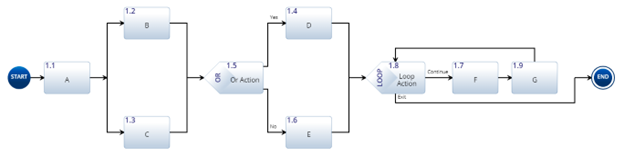 Figure 1: One-Level Action Diagram
From there, equivalent constructs were used in BPMN to create the following Process Diagram.
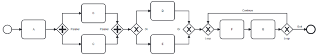
Figure 2: One-Level BPMN Process Diagram
Looking at the diagram elements from left to right, both diagrams begin with a Start node for the Action Diagram and a Start Event for the BPMN Process Diagram. In figure 1, the rectangular elements are Actions which are translated to the rectangular Task elements in the BPMN Process Diagram of Figure 2. The Parallel branches that have elements B and C in Figure 1 require two parallel gateways in BPMN, and the Or Action with elements D and E requires two exclusive gateways in BPMN. The Loop Action containing elements F and G requires two exclusive gateways: one to start the loop that converges incoming flows and one to end the loop that diverges the flow into continue or exit flows. Both diagrams end with an End node for the Action Diagram and an End Event for the BPMN Process Diagram.
Case 2: Action Diagram with Decompositions
This case included a two-level Action Diagram with the second level of element A, shown in Figure 3, to be decomposed into a diagram similar to the diagram in the first case, shown in Figure 5. Figures 4 and 6 show the equivalent BPMN Process Diagrams.
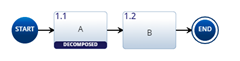
Figure 3: Top-Level Action Diagram
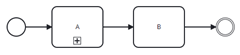
Figure 4: Top-Level BPMN Process Diagram
In the top-level diagram, since Action A in Figure 3 is decomposed, it is equivalent to sub-process A in Figure 4, which can be expanded to show the containing process or collapsed as shown. The process contained in element A is shown below as an Action Diagram and a BPMN Process Diagram.
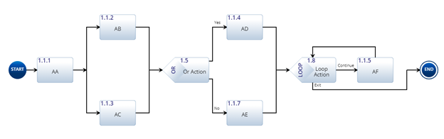 Figure 5: Decomposed Action Diagram
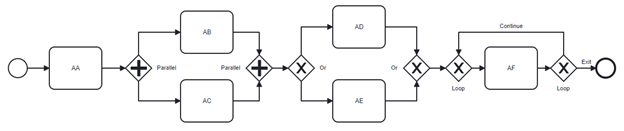
Figure 6: Decomposed BPMN Process Diagram
Case 3: Action Diagram with Asset Branches
This case included an Action Diagram consisting of Actions communicating with Input/Outputs on three Asset Branches, shown in Figure 7. Since it shows communication between different Assets, it is modeled using a BPMN Collaboration Diagram, shown in Figure 8.
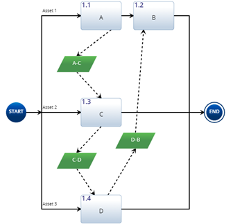
Figure 7: Action Diagram with Branches
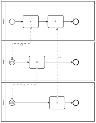
Figure 8: BPMN Collaboration Diagram
The BPMN Collaboration Diagram consists of Pools that represent Participants in a process. The Participants named on each Pool correlate to each of the Asset Branches in Figure 7. Since Sequence Flows are not allowed to cross the boundaries of Pools, Message Flows are used to trigger elements in another Pool. In the Action Diagram, each branch comes from one start node, but in BPMN each pool must have its own start. To account for this and maintain the process order, the Pool with the initial step has a Start Event and the other Pools have Message Events with incoming Message Flows. The Message Events are Start Events with a Message Event Definition that references the incoming Message.
Case 4: Decomposed Action Diagram has Asset Branches
This case included a parent Action Diagram that has Asset Branches where one of the Actions in the diagram is decomposed into another Action Diagram; for example, if Action A in Figure 7 was decomposed. This case is infeasible as Pools in BPMN are only allowed at the top of the hierarchy. For Action Diagrams in this case, the parent and child diagrams would be separated.
The Mapping
The following table shows the complete mapping between LML and BPMN as a result of the cases discussed above. Below are some additional elements included in the table that were not discussed above.
|
LML |
BPMN |
|
Action Diagram with Asset Branches |
Collaboration |
|
Action Diagram without Asset Branches Contains the actions on an asset Branch Contains actions of parents and their children |
Process |
|
Action with Children |
Sub-Process |
|
Action with No Children |
Task |
|
Asset from Asset Branch |
Pool/Participant |
|
Parallel |
Parallel Gateway |
|
Sync |
Exclusive Gateway |
|
Or |
Exclusive Gateway |
|
I/O |
Message Flow / Message |
|
Start |
Start Event / Message Event |
|
End |
End Event |
|
Control Flow |
Sequence Flow |
|
Description |
Documentation |
Sources:
https://www.lucidchart.com/pages/bpmn
https://en.wikipedia.org/wiki/Business_Process_Model_and_Notation
https://www.ibm.com/cloud/blog/bpmn
.png?height=200&name=Untitled%20design%20(48).png)